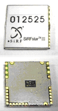
UMTI-08 GPS Engine Module
Features
-
Hardware Specification -2
- Technical Specification -2
- Physical Specification -2
- Recommend PCB Layout -3
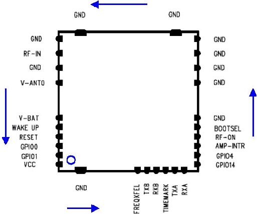
- Module Pin Assignments and Description Table -3
-
Electrical Specifications -6
- Absolute Maximum Ratings -6
- Operating Conditions -6
- The Block Diagram of Module -7
-
Application Schematics -8
- For Active Ant. -8
- For Patch Ant. -8
- NMEA-0183 Output Message -8
- Reflow Profile -9
1. Hardware Specification
1.1 Technical Specification
- Chipset SiRF StarⅢ(GSC3f/LP) Chipset
- Receiver L1( 1575.42MHz), C/A code
- Channels 20CH
- Solution Update Rate 1/second
-
Acquisition
- Hot Start < 8 seconds average, TTFF (Open sky)
- Warm Start < 38 seconds average, TTFF ( Open sky)
- Cold Start < 60 seconds average, TTFF ( Open sky)
-
Limits
- Maximum Altitude 18000m
- Maximum Acceleration 4g
- Maximum Velocity 515m/s
-
Power Consumption 〈 75mA (RF Section 36mA + Digital Section 39mA)
- Input voltage : DC 3.3V ± 5%
-
GPS Software : GSW 3 Ver. 3.2.2
- Protocols COM A : NMEA Protocols
- Serial Port 1 channel – CMOS level
- Baud Rate 4,800 to 115,200 bps adjustable ( default : 9,600)
- Firmware Upgrade 4Mbit Flash Memory field programming S/W available
- Position Accuracy <10m, Without SA imposed (95%)
- Tracking Sensitivity : -155dBm
- Datum Standard : WGS-84
| Pin No. | Signal name | I/O | Description | Note |
| 1 | VCC | PWR | Power Supply Voltage | 3.0~5.0V DC Supply input |
| 2 | GND | PWR | Ground | |
| 3 | FREQXFEL | I | External CMOS clock source | |
| 4 | TXB | O | Serial outputs for channel B | |
| 5 | RXB | I | Serial inputs for channel B | |
| 6 | TIMEMARK | I/O | 1 pps timemark output | |
| 7 | TXA | O | Serial outputs for channel A | |
| 8 | RXA | I | Serial inputs for channel A | |
| 9 | GPIO 14 | I/O | General Purpose Input Output | Leave unconnected if not used |
| 10 | GPIO 4 | I/O | General Purpose Input Output | Leave unconnected if not used |
| 11 | AMP-INTR | I/O | External interrupt[0] | Alternate function is GPIO 10 |
| 12 | RF-ON | I | Power control of RF chip. | Leave unconnected if not used |
| 13 | Bootsel | I | Module Boots Port 5.0V : Boot ON N.C : Boot OFF(Normal) |
Module boots into special debug Mode if VCC during reset |
| 14 | GND | PWR | Ground | |
| 15 | GND | PWR | Ground | |
| 16 | GND | PWR | Ground | |
| 17 | GND | PWR | Ground | |
| 18 | GND | PWR | Ground | |
| 19 | GND | PWR | Ground | |
| 20 | GND | PWR | Ground | |
| 21 | GND | PWR | Ground | |
| 22 | RF IN | I | GPS RF Input | 50Ω (1.57542GHz) |
| 23 | GND | PWR | Ground | |
| 24 | V-ANT0 | PWR | Power supply out of Active antenna | |
| 25 | V-BAT | PWR | BackupVoltage supply for RTC and SRAM | Leave unconnected if not used |
| 26 | WAKE UP | OD | Wake up from RTC (Open Drain) | Leave unconnected if not used |
| 27 | RESET | I/O | Active low reset | Leave unconnected if not used |
| 28 | GPIO0 | I/O | General Purpose Input Output | Leave unconnected if not used |
| 29 | GPIO1 | I/O | General Purpose Input Output | Leave unconnected if not used |
RESET
An external reset is initiated by pulling RESET low for at least 1 µs. If not used, RESET can be left unconnected since there is an internal 10k pull-up resistor. RESET is also used in Push-to-Fix mode in order to wake up the unit and request a position fix. Minimum pulse width is 1 µs.
BOOTSEL
The boot signal BOOTSEL forces special debug mode when restarted with a reset signal or power-up. If not used, BOOTSEL can be left unconnected since there is an internal 100k pull-down resistor.
RF IN
The line on the PCB from the antenna (or antenna connector) has to be a controlled impedance line (Microstrip at 50Ω). br
VBAT
This is the battery backup supply that powers the SRAM and RTC when power is removed. Without an external backup battery or on board battery, engine board will execute a cold start after every turn on. To achieve the faster start-up offered by a hot or warm start, either a backup battery must be connected or battery installed on board.
TIMEMARK
This pin provides one pulse per second output from the engine board which is synchronized to within one microsecond of GPS time. The output is TTL negative level signal with negative logic.
3. Electrical Specifications
3.1 Absolute Maximum Ratings
Warning – Stressing the device beyond the “Absolute Maximum Ratings” may cause permanent damage. These are stress ratings only. Operation beyond “Operating conditions” is not recommended and extended exposure beyond the “Operating condition” may affect device reliability. This module is not protected against over voltage, reversed voltage or short current of RF_IN port.
| Parameter | Min | Max | Unit |
|---|---|---|---|
| Power supply voltage(VCC) | 3.0 | 5.5 | V |
| Serial port input voltage | -0.3 | 5.0 | V |
| BOOTSEL input voltage | -0.3 | 3.6 | |
| Storage temperature | -65 | 150 | ℃ |
4. Operating Conditions
4.1. DC Characteristics (Test Temperature : 25℃)
| Parameter | Condition | Min | Typ | Max | Unit |
|---|---|---|---|---|---|
| Power Supply voltage (Module input power) |
VCC | 3.0 | 3.3 | 5.0 | V |
| Operating supply voltage (SiRF StarⅢ Chipset) |
VCC_RF VDD_BB | 2.7 | 2.85 | 3.0 | V |
| Operating supply ripple voltage | 50 | mVpp | |||
| BOOTSEL input voltage | BOOTSEL | 2.7 | 2.85 | 3.0 | V |
| External Antenna output voltage | V-ANT0 | 2.7 | 2.85 | 3.0 | V |
| Backup battery input voltage | V_BAT | 2.0 | 3.0 | 3.3 | V |
| Sustained supply current | VCC=5.0V | 70 | mA | ||
| Peak supply current | VCC=5.0V | 87 | mA | ||
| Operating temperature | VCC=5.0V | -40 | +25 | +85 | ℃ |
5. The Block Diagram of Module
6. Application Schematics
- NMEA-0183 Output Message
MTI-8 module support a subset of the NMEA-0183 standard for interfacing marine electronic devices as defined by the National Marine Electronics Association (NMEA). - NMEA Output messages
The following is written assuming the user has a basic understanding of NMEA protocols and their use. - GGA : Time, position and fix type data.
- GLL : Latitude, longitude, UTC time of position fix and status.
- GSA : GPS receiver operating mode, satellites used in the position solution, and DOP values.
- GSV : The number of GPS satellites in view satellite ID numbers, elevation, azimuth, and SNR values.
- MSS : Signal-to-noise ratio, signal strength, frequency, and bit rate from a radio-beacon receiver.
- RMC : Time, date, position, course and speed data.
- VTG : Course and speed information relative to the ground.
- ZDA : PPS timing message (synchronized to PPS).


